|
MeshKit
1.0
|
|
MeshKit
1.0
|
The general idea of graph-based mesh generation was discussed in the previous section. Here, we give a few more realistic examples of applying the graph-based approach to mesh generation. Currently, most of the meshing operations desribed below have not yet been implemented in MeshKit. These examples are useful, though, for understanding how a graph-based approach applies to other kinds of problems.
In this example, a single volume is meshed with a one-to-one sweep algorithm. The geometric model is a simple cylinder, with edges C1, C2, surfaces S1, S2, S3, and volume V1:
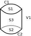
Here, we ignore the two vertices bounding the curves; their meshing is done in the same way discussed in the previous example.
The user input for this example consists of two graph nodes, one specifying that the volume be meshed with SweepMesh, the other specifying the QuadMesh algorithm for one of the surfaces:
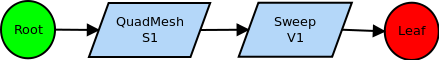
We assume here that the sweep algorithm, in its setup_this method, can find the proper source and target surfaces for the sweep, perhaps using the Automatic sweep detection algorthm (White&Tautges, '96).
In the sweep algorithm setup phase, a graph node is added to map-mesh surface S3, and surface S2 is added to the model entities treated by the SweepMesh node. Proceeding with the setup traversal (in the reverse direction), the QuadMesh/S1 and MapMesh/S3 nodes each add a node for edge-meshing the edges C1 and C2. Each graph node also adds a dependency on a single IntervalMatch graph node, which appears as the first (non-trivial) node in the graph. The final graph after setup is completed is:
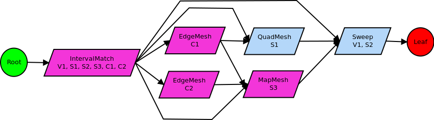
Note that the graph node for meshing geometric vertices is not shown here. Also, in contrast to previous examples where a single EdgeMesh node was used, in this graph we use separate nodes, to emphasize that one surface node depends on both EdgeMesh nodes, while another surface depends on only one.
The execution phase proceeds in the normal manner, calling interval matching, then generating mesh for C1, C2, S1, S3, and V1/S2.
Now, consider the situation where the user would like to change the mesh on C2, perhaps to bias the mesh towards the geometric vertex. This would invalidate the graph node corresponding to EdgeMesh/C2. According to the mesh graph rules that were discussed earlier, this would also invalidate all descendents in the graph, in this case SweepMesh/V1,S2. This would not invalidate QuadMesh/S1, since that node does not depend on the node being invalidated. Re-execution of the graph, after modifying the input parameters on EdgeMesh/C2, would visit only EdgeMesh/C2 and SweepMesh/V1,S2. In this way, we see that the nodes requiring invalidation and re-execution can be determined directly by traversing the graph from the node being invalidated.
In this example, we use the same single-cylinder geometric model as the previous example, but use automatic scheme detection to assign all meshing schemes. The user-specified portion of the mesh graph is quite simple, consisting of a single AutoScheme/V1 node:
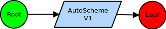
The actions of the setup_this function for this case are much more detailed than in previous examples. First, before performing automatic scheme detection on the volume, automatic scheme detection must be performed on all surfaces bounding the volume. We represent this using distinct AutoScheme nodes for each surface S1, S2, S3. After creating these nodes and making them ancestors of the AutoScheme/V1 node, the setup_this functions for the nodes are called from inside the AutoScheme/V1 setup_this function. This is necessary, because automatic scheme detection for the volume depends on the results of automatic scheme detection on the surfaces. Detecting schemes is considered part of the setup phase of mesh generation, since it determines the operations necessary to mesh something rather than generating the mesh itself. In this example, the results of automatic scheme detection on surfaces S1, S2, S3 results in graph nodes QuadMesh/S1, QuadMesh/S2, and MapMesh/S3, respectively. These nodes are created by the AutoScheme/S1-S3 nodes, but are made descendents of the corresponding AutoScheme nodes, instead of ancestors. This is because automatic scheme detection for a surface does not depend on the scheme selected for that surface, but vica versa (the selected scheme depends on the automatic scheme detection). After completing the setup functions on the AutoScheme/S1-S3 nodes, the graph looks like:
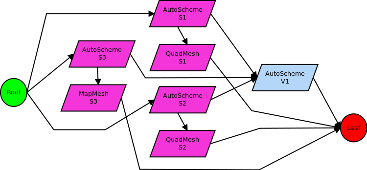
Here, we leave out graph nodes for edge and vertex meshing, for brevity. Several things should be noted in this figure. First, the QuadMesh/S1-2 nodes are connected directly to the leaf node. This is because the AutoScheme/V1 setup_this function has not completed; eventually, at least some of those nodes will be connected to a node for meshing the volume. Second, the QuadMesh/S1-2 and MapMesh/S3 nodes are not ancestors of the AutoScheme/V1 node. Automatic scheme detection for the volume depends on the action of the AutoScheme/S1-S3 nodes, but not on those of the actual schemes selected. That is, automatic scheme selection for the volume depends on the type of mesh scheme selected, but not on the mesh actually generated by those schemes.
After all surface schemes have been selected, the AutoScheme/V1 setup_this function can complete its task. The result is the selection of a sweep scheme, generating mesh for both V1 and S2:
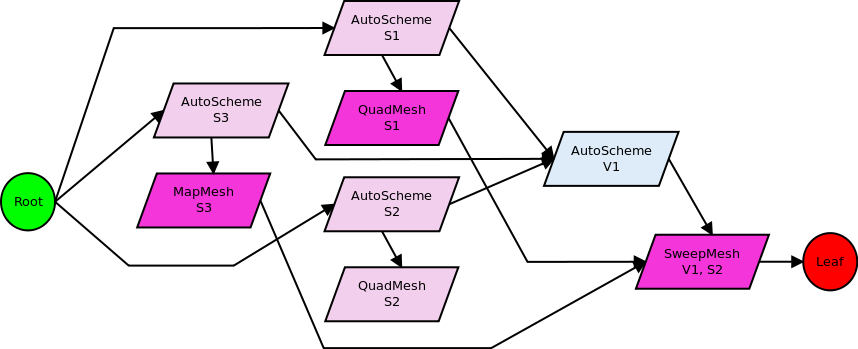
However, we cannot simply add this node to the graph, since then two nodes would be responsible for generating mesh on S2. Rather, in selecting a sweep scheme for V1, automatic sweep detection also removes the QuadMesh/S2 node from the graph. Once the SweepMesh/V1,S2 node has been created, it is made a direct descendent of QuadMesh/S1 and MapMesh/S3, but not the AutoScheme/S1,S3 nodes. Again, the actual generation of mesh on V1 and S2 does not depend on the schemes selected for those surfaces, but just the mesh on those surfaces.
One other curious thing in this mesh graph is that several of the nodes only do meaningful work during their setup_this function. Their execute_this functions are simply pass-throughs, not performing any work but indicating the graph edges along which traversal must proceed. A topological sort-based traversal ensures that none of the mesh generating nodes will be executed before all their predecessors have completed execution.
Top: MeshKit: A Library for Mesh Generation Prev: A Graph-Based Model for Mesh Generation Next: Geometry, Mesh, Relations Interfaces
 1.7.6.1
