|
MeshKit
1.0
|
|
MeshKit
1.0
|
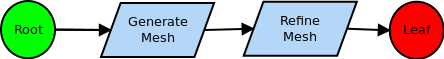
MeshKit is designed around a graph-based view of the meshing process. What is a graph-based view? If you're used to a meshing process built around BREP-based geometry (e.g. like the one used in CUBIT and other solid modeler-based meshing tools), you're probably used to the idea of meshing BREP entities in increasing dimension, i.e. the geometric vertices, then edges, then faces, then regions. In this case, the graph is the topology graph, with graph nodes corresponding to geometric entities, and graph edges the adjacency relationships between entities. When the BREP is the graph, each meshing operation is synonymous with the geometric entity it operates on. However, this is only a special case of a graph-based process; more generally, each meshing operation can be a node in the graph, with graph edges representing dependencies between operations. For example, in the case of meshing then refinement, the graph would have two nodes, one for generating the initial mesh, and the other for refining that mesh. The (single) edge linking the two nodes represents the dependency between these operations. In other words, you can't perform the refinement operation until you have something to refine. A graphical representation of this graph is:
MeshKit represents the meshing process as a single directed, acyclic graph (DAG). The graph always has a single root and leaf node; this is for convenience, so that traversals always begin at one node and end at another. When a meshing operation is instantiated in MeshKit, it is automatically made a child of the root node and a parent of the leaf node. The node can then be inserted elsewhere in the graph, making it a child/parent of other nodes (often disconnecting the node from the root and/or leaf nodes). Any meshing operation (implemented in a class derived from MeshOp) can be a node in the graph.
Using the graph, the meshing process is implemented as two phases: a "setup" phase, when the graph is traversed in the reverse direction from the leaf to the root node; and an "execute" phase, when the graph is traversed in the forward direction, from the root to the leaf node. During the setup phase, a meshing operation examines the model entity(ies) it is assigned to, possibly creating other meshing operations on which it depends. These new meshing operations are inserted in the graph, upstream of the meshing operation / graph node being examined. Since the new nodes are inserted upstream, that means the current node depends on those operations. The Setup phase traverses up the graph in a "topological sort" order, in the process visiting any new graph nodes (and any new nodes those nodes produce), until the root node is visited. After the Setup phase is completed, the graph is traversed in the forward direction, again in a topological sort order, starting at the root node and ending at the leaf node. This phase is called the Execute phase, where mesh is generated (or operated on, depending on the type of meshing operation in each graph node). Traversing in a topological sorted order ensures that all dependencies for a given node have been executed before that node is visited.
Using a graph-based approach for the meshing process has several advantages over the more traditional BREP-based method:
A more detailed example of graph traversal is given here. Some more graph-based meshing examples are found here.
 1.7.6.1
